Creating LOD Models: Difference between revisions
add more images |
Nbohr1more (talk | contribs) |
||
| (13 intermediate revisions by 2 users not shown) | |||
| Line 1: | Line 1: | ||
== Introduction == | == Introduction == | ||
TDM from v1.03 onwards has a LOD system, where the engine can replace models that are far away with simpler versions. The same technique can also be applied manually, by placing decals at some distance to create the illusion of more details. | |||
This article details how to create models that can be used for such purposes and what the performance gains are. | This article details how to create models that can be used for such purposes and what the performance gains are. | ||
| Line 13: | Line 13: | ||
=== Start with a suitable model === | === Start with a suitable model === | ||
I | Select a model that: | ||
* has sufficiently high number of polys (anything > 100) OR has a many surfaces (> 2) | |||
* will be used in places that will be both far away and near the player in one mission | |||
* Is compact and possible symmetric from all sides | |||
I started with the ''cattails4.low'' model as example, as I am using it in a map of my own. | |||
{{clear}} | {{clear}} | ||
=== Create screenshots from DR === | === Create screenshots from DR === | ||
| Line 21: | Line 28: | ||
[[Image:Cattails green 4 with patch.png|right|thumb|240px]] | [[Image:Cattails green 4 with patch.png|right|thumb|240px]] | ||
I put the model into a map, removing everything that was visible behind it | I put the model into a map (see at the [[#See also|bottom]] for an archive with pre-made maps with black rooms), removing everything that was visible behind it. | ||
Then either: | |||
* just use the grey background from the DR camera window if your model doesn't contain this sort of grey | |||
* '''OR''' then create a simple patch mesh behind it, and texture it with '''textures/sfx/white''' or '''textures/darkmod/sfx/black_matt'''. When you select this patch in DR, it gives a nice uniform brown color, or you can use the black version. Use the version where the background clashes the least with your model's colors. | |||
The idea here is that which we can later separate the background from the model itself in Gimp easily be just selecting the background color. | |||
''' | '''Notes:''' | ||
* Draw the camera view from DR as big as possible to capture the highest quality possible. | |||
* Use the "View => Camera => Center" option from the DR menu (or use {{key|END}}) to level the camera after moving it at the center line of the model. | |||
* If you use a patch, make sure you put the patch completely behind the model. | |||
* If your model has skins, it is best to switch skins and make one screenshot for each skin without adjusting the camera. This way all the skin screenshots will align perfectly without any extra work, and you only need to position the camera once for each shot. | |||
Then I used the screen capture program from KDE to create screenshots and open them up in Gimp. One shot from the front, one from the side. Try to align the camera as level and at the center of the model as possible. The exact alignment isn't nec, but it simplifies things somewhat. | Then I used the screen capture program from KDE to create screenshots and open them up in Gimp. One shot from the front, one from the side. Try to align the camera as level and at the center of the model as possible. The exact alignment isn't nec, but it simplifies things somewhat. | ||
'''Tips:''' | |||
* The KDE screenshot applet has a handy "Open with ... Gimp" button for this so you can take all screenshots and load them in Gimp without saving them first to disk). | |||
* If you model is somewhat symmetric, a front and side view are enough. If it looks too different from the front and back, f.i., you might also want to crate a back-side and a back view. | |||
{{clear}} | {{clear}} | ||
=== The texture === | === The texture === | ||
| Line 36: | Line 59: | ||
# Cut out the model, the size does not matter yet: | # Cut out the model, the size does not matter yet: | ||
# Select "Select by similiar colors" and click on the brown, then fill the selection with black: | # Select "Select by similiar colors" and click on the brown or grey background, then fill the selection with black: | ||
# Now "Resize the canvas". That means you change the dimensions of the image, but don't scale it! Select as a size that fits closely (but not pixel-perfect), and is either square, or in my case 2:1 or 1:2. | # Now "Resize the canvas". That means you change the dimensions of the image, but don't scale it! Select as a size that fits closely (but not pixel-perfect), and is either square, or in my case 2:1 or 1:2. | ||
# Add a mask to the current layer. | # Add a mask to the current layer. | ||
| Line 44: | Line 67: | ||
Done for now in Gimp. | Done for now in Gimp. | ||
[[Image:Decal 01.png|100px|Step 1]] [[Image:Decal fill whole selection with black.png|100px|Step 2]] [[Image:Decal resize canvas.png|100px|Step 2]] [[Image:Decal layer to image size fill border.png|100px|Step 3]] [[Image:Decal layer mask.png|120px|Step 4]] [[Image:Decal transparent.png|100px|Step 5]] [[Image:Decal scale.png|100px|Step 6]] | [[Image:Decal 01.png|100px|Step 1]] [[Image:Decal fill whole selection with black.png|100px|Step 2]] [[Image:Decal resize canvas.png|100px|Step 2]] [[Image:Decal layer to image size fill border.png|100px|Step 3]] [[Image:Decal layer mask.png|120px|Step 4]] [[Image:Decal transparent.png|100px|Step 5]] [[Image:Decal scale.png|100px|Step 6]] | ||
| Line 51: | Line 72: | ||
{{clear}} | {{clear}} | ||
---- | ---- | ||
[[Image:Decal atlas.png|right|200px]] | [[Image:Decal atlas.png|right|200px]] | ||
| Line 58: | Line 81: | ||
{{clear}} | {{clear}} | ||
=== The material definition === | === The material definition === | ||
| Line 89: | Line 113: | ||
blue global4 | blue global4 | ||
} | } | ||
{ | |||
} | |||
</pre> | |||
Note: This section: | |||
<pre> | |||
{ | |||
if (global5 == 2) | if (global5 == 2) | ||
blend add | blend add | ||
| Line 98: | Line 130: | ||
vertexParm 3 0 | vertexParm 3 0 | ||
fragmentMap 0 cubeMap env/gen1 | fragmentMap 0 cubeMap env/gen1 | ||
fragmentMap 1 | fragmentMap 1 _flat // Bump | ||
fragmentMap 2 textures/darkmod/decals/vegetation/cattail_flat_side // Diffuse | fragmentMap 2 textures/darkmod/decals/vegetation/cattail_flat_side // Diffuse | ||
fragmentMap 3 _black | fragmentMap 3 _black // Specular | ||
} | } | ||
</pre> | </pre> | ||
'''Note:''' If you make the material two-sided, then you can save creating the "backside" patch. However, D3 will do so when it loads any model using this material, and the "backside" is created as an extra surface. This means it will use up one extra drawcall. To avoid this, we create a one-sided material, and create the backside | has been removed as it is no longer needed as of TDM 2.0 (Standalone) | ||
'''Note:''' If you make the material two-sided, then you can save creating the "backside" patch. However, D3 will do so when it loads any model using this material, and the "backside" is created as an extra surface. This means it will use up one extra [[drawcalls|drawcall]]. To avoid this, we create a one-sided material, and create the backside ourselves: | |||
=== Create the patches, export as ASE === | === Create the patches, export as ASE === | ||
Now we are back to DR: | |||
# Create a patch mesh (3x3) and place it inside your model, at the middle, and drag it out so it covers the model dimensions | |||
# Select the newly made material, and in the surface inspector, press "Fit". You might also have to flip the texture vertically. If you created a texture atlas, you also need to scale the texture to '''0.5 x 1.0''' and use the '''Right''' and '''Left''' buttons on the surface inspector. | |||
# Now repeat this step from the other side, e.g. 90°,creating the side-texture and a side patch. | |||
# You will end up with something like this, the two patches, and the original model in the middle: | |||
# If you have created a one-sided material (as you should :), select each of the patches, duplicate it with {{key|SPACE}} and then rotate them around the z-axis by 180°. This makes sure the model is visible from all angles. | |||
# Now deselect the original model, and export all (two or four) patches as ASE model. The origin should match the origin of the original model (e.g. not be nec. at 0,0,0). The easiest way to select all patches is to draw a brush around the model (enclosing it completely), then select "Select inside". Don't forget to deselect the original model, you want only the patches! Re-import the model into DR and you are now almost done. | |||
{{clear}} | |||
[[Image:Cattails green 4 with patch 2.png|240px|Step 1]] [[Image:Cattails done.png|240px|Step 5]] [[Image:Decal atlas1.png|240px|Step 6]] [[Image:Cattails done2.png|240px|Step 6]] | |||
[[Image:Cattails side by side 2.png|240px|Done!]] [[Image:Cattails side by side.png|240px|Done!]] | |||
'''Note:''' In some of the screenshots above, the patches are not exactly center in the model, this was a mistake of mine and has been corrected after I took the screenshots. | |||
{{clear}} | |||
=== The model in game === | === The model in game === | ||
These shots show the models side by side in game. Note that the conditions here are unrealistic, the model will never be seen so close by the player, and in addition, one would choose a dark background/underground to hide the models better. | |||
As you can see on the second shot, where the largest distance is 1000 units, the model will be indistinguishable in most conditions. (Note: The cattails screenshot are before color correction, this is why the LOD model looks quite a bit darker) | |||
[[Image:Ingame side by side.jpg|360px|Done!]] [[Image:Ingame side by side 2.jpg|360px|Done!]] | |||
[[Image:Ingame org.jpg|360px|Original model in game]] [[Image:Ingame new.jpg|360px|New model in game]] | |||
[[Image:Ingame org tris.jpg|360px|Original model in game]] [[Image:Ingame new tris.jpg|360px|New model in game]] | |||
{{clear}} | |||
And here is a screenshot from a lily model: | |||
[[Image:Ingame lilies compare.jpg|360px|Side by Side lilies]] | |||
{{clear}} | |||
=== Color correction === | |||
When you look at your model in game, it might appear to dark compared to the original model. The cattails are f.i. ok, but the lily looks off: | |||
[[Image:Lily before colorcorrect.png|360px|Lily model before color correction]] | |||
This can be corrected by adjusting the colors of the texture, f.i. by using the "Curves" tool. I used the original texture here a a rough guideline. The exact match is not that important, just get it close: | |||
[[Image:Lilies color correct.png|420px|Collor coretion with the Curves tool]] | |||
'''Result:''' | |||
[[Image:Lily after colorcorrect.png|360px|Lily model in game after color correction]] | |||
== Optimizing == | == Optimizing == | ||
If you haven't followed the steps about a ''texture atlas'' and created a two-sided material, you will notice that the model uses 4 [[drawcalls]] in game, compared to the original model. That means placing many of the new models is actually slower than placing the original models, despite the greatly reduced number of triangles. | |||
The reasons are: | |||
* Without a texture atlas, each patch uses its own material, thus creating two surfaces, using one [[drawcalls|drawcall]] each. | |||
* With a [[twosided|two-sided]] material, D3 will upon load duplicate all surfaces and invert their side. This means you end up with 2 drawcalls instead of one. | |||
Both issues together will create '''four drawcalls per model per light''', instead '''one per model per light'''. Since each model is drawn multiple times (once for each light), this can add up very fast. | |||
Here is how you can fix this: | |||
=== Texture atlas === | === Texture atlas === | ||
# Create both views (side and front) in the same texture. | |||
# Select the newly made material, and in the surface inspector, enter "0.5 x 1.0" for the scale, then press "Fit". use the "Left" and "Right" buttons to shift the texture for the front and side, respectively. | |||
Here are some tips for creating a good texture atlas: | |||
The texture atlas should have equal space for each texture part. This makes it easier to positioning things in the editor when texturing the patches. However, sometimes this is not possible. Here is an example of the lily model,where one side view is quite a bit larger than the others: | |||
[[Image:Lily attempt 1.png|500px|border|Lily model in game before color correction]] | |||
There are two ways to fix this: | |||
# make everything the same size (in this case 1/4 of the texture). This means that the left three parts are sourounded by quite big empty spaces, wasting texture resolution. | |||
# Make the "offending" part smaller. This means you need some scaling to get it back to size when texturing, and it also has not the same resolution as the other parts. The advantage is, however, that the other parts all use the resolution much better. | |||
Here is how #2 looks: | |||
[[Image:Lily attempt 2.png|500px|border|Size corrected atlas]] | |||
And the final texture atlas: | |||
[[Image:Lily atlas.png|500px|border|Final atlas]] | |||
=== One-sided material with duplicated patches === | === One-sided material with duplicated patches === | ||
{{ | # Uncomment the "twosided" line in your material. | ||
# Select each of the two patches, duplicate it with {{key|SPACE}} and then rotate them around the z-axis by 180°. This makes sure the model is visible from all angles. | |||
== Remarks == | |||
In my first test, I also did a "top-side" view, and placed this as patch at the bottom, horizontally. The theory was that there is something the player can see if he looks straight from the top. | |||
However, in game tests showed that it only looked funky (often z-fighting with the floor), and since the player is far away from the model, anyway, he can't see it from straight top. If you view it high above, it will still look quite good due to the patch being vertical and thus partly visible. So, just having a front and side few is sufficient for high models. | |||
However, if the model is very small (like only 20cm high) and the player can walk over the model and view it straight from the top, you should consider adding a horizontal plane, too. Make sure you lift if 0.0125 units above the floor, tho, or it will z-fight with the floor! | |||
== See also == | == See also == | ||
* The [[LOD]] system | * The [[LOD]] system | ||
* [[List of LOD Models]] | |||
* [[SEED]] | |||
* [[twosided]] - Visual explanations on how twosided surfaces work | |||
* http://en.wikipedia.org/wiki/Texture_atlas | * http://en.wikipedia.org/wiki/Texture_atlas | ||
* [http://bloodgate.com/mirrors/tdm/pub/lod_construction.zip Helper maps with black room and fixed camera pos] | |||
{{editing}} {{scripting}} | {{editing}} {{scripting}} | ||
Latest revision as of 16:00, 14 May 2017
Introduction
TDM from v1.03 onwards has a LOD system, where the engine can replace models that are far away with simpler versions. The same technique can also be applied manually, by placing decals at some distance to create the illusion of more details.
This article details how to create models that can be used for such purposes and what the performance gains are.
The tutorial assumes you use Gimp, but a similiar technique will work with Photoshop or any other image editing program.
Creating the model
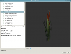
Start with a suitable model
Select a model that:
- has sufficiently high number of polys (anything > 100) OR has a many surfaces (> 2)
- will be used in places that will be both far away and near the player in one mission
- Is compact and possible symmetric from all sides
I started with the cattails4.low model as example, as I am using it in a map of my own.
Create screenshots from DR
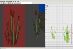
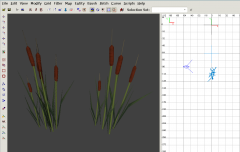
I put the model into a map (see at the bottom for an archive with pre-made maps with black rooms), removing everything that was visible behind it.
Then either:
- just use the grey background from the DR camera window if your model doesn't contain this sort of grey
- OR then create a simple patch mesh behind it, and texture it with textures/sfx/white or textures/darkmod/sfx/black_matt. When you select this patch in DR, it gives a nice uniform brown color, or you can use the black version. Use the version where the background clashes the least with your model's colors.
The idea here is that which we can later separate the background from the model itself in Gimp easily be just selecting the background color.
Notes:
- Draw the camera view from DR as big as possible to capture the highest quality possible.
- Use the "View => Camera => Center" option from the DR menu (or use END) to level the camera after moving it at the center line of the model.
- If you use a patch, make sure you put the patch completely behind the model.
- If your model has skins, it is best to switch skins and make one screenshot for each skin without adjusting the camera. This way all the skin screenshots will align perfectly without any extra work, and you only need to position the camera once for each shot.
Then I used the screen capture program from KDE to create screenshots and open them up in Gimp. One shot from the front, one from the side. Try to align the camera as level and at the center of the model as possible. The exact alignment isn't nec, but it simplifies things somewhat.
Tips:
- The KDE screenshot applet has a handy "Open with ... Gimp" button for this so you can take all screenshots and load them in Gimp without saving them first to disk).
- If you model is somewhat symmetric, a front and side view are enough. If it looks too different from the front and back, f.i., you might also want to crate a back-side and a back view.
The texture
We now work in Gimp:
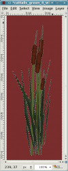
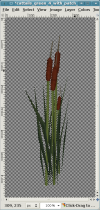
- Cut out the model, the size does not matter yet:
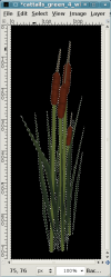
- Select "Select by similiar colors" and click on the brown or grey background, then fill the selection with black:
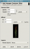
- Now "Resize the canvas". That means you change the dimensions of the image, but don't scale it! Select as a size that fits closely (but not pixel-perfect), and is either square, or in my case 2:1 or 1:2.
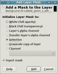
- Add a mask to the current layer.
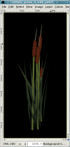
- You should end up with a view like this.
- Now scale the image so it is a power of 2. Don't go higher than 512, as this is a texture for a model far away. Even 256 pixels might be sufficient.
Done for now in Gimp.
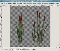
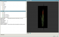
Note: To avoid having to redo some steps, create both views (side and front) in the same texture. This is called a "texture-atlas" and improves performance, see the section about Optimizing for more info:
The material definition
Create a material definition, here is an example:
textures/darkmod/decals/vegetation/cattails_green4_side
{
    qer_editorimage textures/darkmod/decals/vegetation/cattail_flat_side
    surftype15
    description "foliage"

    // twosided  // See later section about optimizing!
    nonsolid

    {
        blend diffusemap
        map textures/darkmod/decals/vegetation/cattail_flat_side
        alphatest 0.5
    }

    // TDM Ambient Method Related
    {
        if (global5 == 1)
        blend add
        map             textures/darkmod/decals/vegetation/cattail_flat_side
        scale           1, 1
        red         global2
        green           global3
        blue            global4
    }

}
Note: This section:
{
        if (global5 == 2)
        blend add
        program ambientEnvironment.vfp
        vertexParm      0       1, 1, 1, 1      // UV Scales for Diffuse and Bump
        vertexParm      1       1, 1, 1, 1  // (X,Y) UV Scale for specular, Z: ambient reflection scale
        vertexParm      2       global2, global3, global4, 1
        vertexParm      3       0
        fragmentMap     0       cubeMap env/gen1
        fragmentMap     1       _flat                                                 // Bump
        fragmentMap     2       textures/darkmod/decals/vegetation/cattail_flat_side  // Diffuse
        fragmentMap     3       _black                                                // Specular
    }
has been removed as it is no longer needed as of TDM 2.0 (Standalone)
Note: If you make the material two-sided, then you can save creating the "backside" patch. However, D3 will do so when it loads any model using this material, and the "backside" is created as an extra surface. This means it will use up one extra drawcall. To avoid this, we create a one-sided material, and create the backside ourselves:
Create the patches, export as ASE
Now we are back to DR:
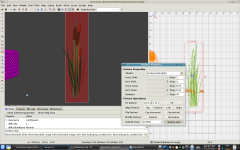
- Create a patch mesh (3x3) and place it inside your model, at the middle, and drag it out so it covers the model dimensions
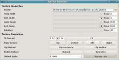
- Select the newly made material, and in the surface inspector, press "Fit". You might also have to flip the texture vertically. If you created a texture atlas, you also need to scale the texture to 0.5 x 1.0 and use the Right and Left buttons on the surface inspector.
- Now repeat this step from the other side, e.g. 90°,creating the side-texture and a side patch.
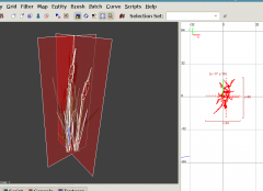
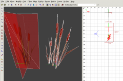
- You will end up with something like this, the two patches, and the original model in the middle:
- If you have created a one-sided material (as you should :), select each of the patches, duplicate it with SPACE and then rotate them around the z-axis by 180°. This makes sure the model is visible from all angles.
- Now deselect the original model, and export all (two or four) patches as ASE model. The origin should match the origin of the original model (e.g. not be nec. at 0,0,0). The easiest way to select all patches is to draw a brush around the model (enclosing it completely), then select "Select inside". Don't forget to deselect the original model, you want only the patches! Re-import the model into DR and you are now almost done.
Note: In some of the screenshots above, the patches are not exactly center in the model, this was a mistake of mine and has been corrected after I took the screenshots.
The model in game
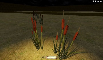
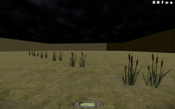
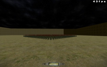
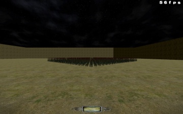
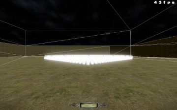
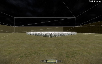
These shots show the models side by side in game. Note that the conditions here are unrealistic, the model will never be seen so close by the player, and in addition, one would choose a dark background/underground to hide the models better.
As you can see on the second shot, where the largest distance is 1000 units, the model will be indistinguishable in most conditions. (Note: The cattails screenshot are before color correction, this is why the LOD model looks quite a bit darker)
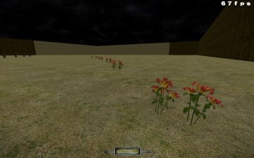
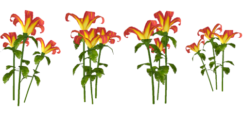
And here is a screenshot from a lily model:
Color correction
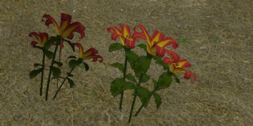
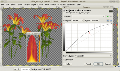
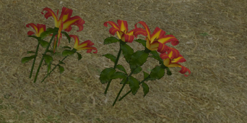
When you look at your model in game, it might appear to dark compared to the original model. The cattails are f.i. ok, but the lily looks off:
This can be corrected by adjusting the colors of the texture, f.i. by using the "Curves" tool. I used the original texture here a a rough guideline. The exact match is not that important, just get it close:
Result:
Optimizing
If you haven't followed the steps about a texture atlas and created a two-sided material, you will notice that the model uses 4 drawcalls in game, compared to the original model. That means placing many of the new models is actually slower than placing the original models, despite the greatly reduced number of triangles.
The reasons are:
- Without a texture atlas, each patch uses its own material, thus creating two surfaces, using one drawcall each.
- With a two-sided material, D3 will upon load duplicate all surfaces and invert their side. This means you end up with 2 drawcalls instead of one.
Both issues together will create four drawcalls per model per light, instead one per model per light. Since each model is drawn multiple times (once for each light), this can add up very fast.
Here is how you can fix this:
Texture atlas
- Create both views (side and front) in the same texture.
- Select the newly made material, and in the surface inspector, enter "0.5 x 1.0" for the scale, then press "Fit". use the "Left" and "Right" buttons to shift the texture for the front and side, respectively.
Here are some tips for creating a good texture atlas:
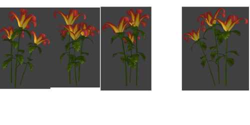
The texture atlas should have equal space for each texture part. This makes it easier to positioning things in the editor when texturing the patches. However, sometimes this is not possible. Here is an example of the lily model,where one side view is quite a bit larger than the others:
There are two ways to fix this:
- make everything the same size (in this case 1/4 of the texture). This means that the left three parts are sourounded by quite big empty spaces, wasting texture resolution.
- Make the "offending" part smaller. This means you need some scaling to get it back to size when texturing, and it also has not the same resolution as the other parts. The advantage is, however, that the other parts all use the resolution much better.
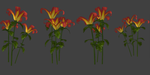
Here is how #2 looks:
And the final texture atlas:
One-sided material with duplicated patches
- Uncomment the "twosided" line in your material.
- Select each of the two patches, duplicate it with SPACE and then rotate them around the z-axis by 180°. This makes sure the model is visible from all angles.
Remarks
In my first test, I also did a "top-side" view, and placed this as patch at the bottom, horizontally. The theory was that there is something the player can see if he looks straight from the top.
However, in game tests showed that it only looked funky (often z-fighting with the floor), and since the player is far away from the model, anyway, he can't see it from straight top. If you view it high above, it will still look quite good due to the patch being vertical and thus partly visible. So, just having a front and side few is sufficient for high models.
However, if the model is very small (like only 20cm high) and the player can walk over the model and view it straight from the top, you should consider adding a horizontal plane, too. Make sure you lift if 0.0125 units above the floor, tho, or it will z-fight with the floor!
See also
- The LOD system
- List of LOD Models
- SEED
- twosided - Visual explanations on how twosided surfaces work
- http://en.wikipedia.org/wiki/Texture_atlas
- Helper maps with black room and fixed camera pos
